Force Servo, Introduction

The invention simplifies many mechanical devices where it's necessary to control the action force created by a servo drive.
This is a usual Position Servo, and this is a Force Servo.
The Position Servo features a position sensor.
The position of the arm is defined by a control signal.
The Force Servo contains an elastic element and a force sensor.
The control signal sets the pressure on the arm regardless of its position.
In position servo, the load abuts against the gearbox.
Due to certain free play in the gearbox, the arm of the position servo experiences vibrations and wobbling when in motion.
In force servo, the load does not abuts against the gearbox and does not suffer from free play.
In this example, a neutral control signal is sent to the Force Servo.
The high sensitivity of the sensor enables the mechanism to respond to the touch of a burnt out match.
A magnetic coupling is installed on this prototype.
The linear hall sensor measures the shift of magnetic poles.
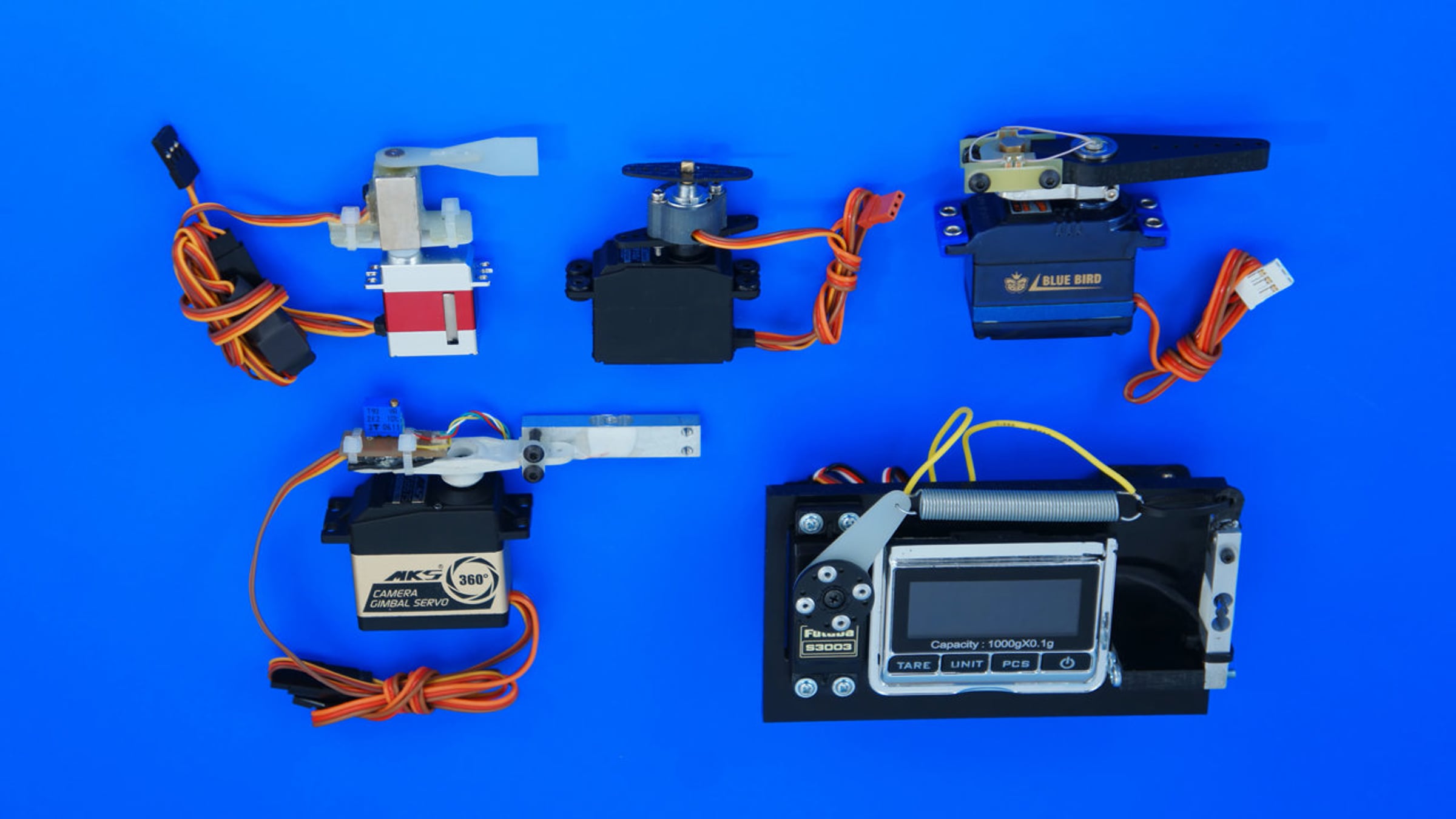
This prototype has a strain-gage sensor.
A force servo can be used in mechanical manipulators of various robots.
Force control makes it possible to accurately grasp fragile items.
This prototype uses force sensing resistors.
Pressure is passed to resistors through silicone dampers.
On this prototype, the spring acts as a sensor.
When the spring is stretched, it’s inductive electrical resistance changes.
An electronic scheme measures the inductance and controls the motor.
Force Servo can be used for camera rotation and stabilization.
This test stand imitates a stabilized platform with a video camera.
The mass of the rotated part is 6 kg.
The maximum rotation speed that this stand can compensate is 180 RPM. The maximum speed of deliberate rotation is 60 RPM.
This lever imitates the swinging of the unstable base.
This modification features an additional reduction gear that raises the torque.
This is the stability test simulating a strong wind flow.
This is another experimental stand.
The mass of the rotating part is 11 kg.
The design uses a magnetic rotation encoder as a force sensor.
During testing, the servo drive first rotates the platform and slows it down afterwards.
The slowdown speed and the level of unwanted vibrations are measured.
This is a prototype of a stabilized platform for a miniature camera.
The platform tilt is controlled by an electronic gyroscope only, without a position sensor.
The electronic gyroscope allows for a smooth slowdown without swaying.
In other words, the pendulum effect is effectively suppressed.
This is the Ecilop Easy drone with a stabilized video camera platform.
External potentiometers are connected to the servo drives.
These potentiometers measure the spring stretching values.
This is how Position Servo units are transformed into Force Servo units.
Force servo drive does not interfere with the inertial stabilization of the platform.
As the result, the servo drive rotates the camera resting on the unstable base, but the tilt of the unstable base makes no sense.
On this drone, the servo drive turns by 60 degrees in 50 milliseconds.
This is much faster than any unwanted platform swaying.
To get higher acceleration, you would have to hit the drone with a baseball.
However, even in this case, the short impulse will be absorbed by the springs installed between the servo drive and the platform.
Force Servo offers fast reaction without mechanical noises of the reduction gear being passed to the platform being stabilized.
If you compare this design with a direct drive brushless motor, Force Servo will have the following advantages:
High torque;
Compact size and weight;
Lower energy consumption;
Scalability for rotation of cameras of any mass;
Possibility to leverage the benefits of inertial stabilization including the use of an additional counterweight or a heavy mechanical gyroscope;
And absence of non-linearity thanks to feedback from the force sensor.
Force servo can be used instead of Position Servo for deflecting a vehicle’s rudders.
On this plane, Force servo deflects the ailerons.
While the plane is on the ground, the ailerons are in a random position.
Once the air starts putting pressure on the rudders, they will automatically assume the neutral position.
The servo drive has an electronic gyroscope connected to it in the Heading Hold mode.
The gyroscope maintains the set roll angle of the plane.
On this boat, Force Servo deflects the direction rudder.
Additional stabilization is provided by a gyroscope in the “normal” mode.
The deflection angle is smaller at a high speed, since the pressure of the water flow is stronger.
Thanks to this fact, low-speed maneuverability is improved, while hypergravity and toppling over in turns are prevented.
Thanks to the force sensor, the servo drive and rudder are protected from mechanical overloads.
Get started for free
24/7 customer support
Our customer support team is available to help 24/7. Enterprise members also receive dedicated account managers and a guaranteed uptime SLA.
© 2026 Vimeo.com, Inc. All rights reserved.
TermsPrivacyYour Privacy ChoicesU.S State PrivacyCopyrightCookies